


Pin Assignment for 1-Wire Devices
Please read the following notes carefully, especially if you plan to combine 1-Wire products with RJ12 or RJ45 connectors from different manufacturers. If pin assignments are not taken into account, devices may not function correctly or may even be damaged in the worst case.
Since not every manufacturer offers the right product for every application, combining devices from different vendors is often desirable. In this article we explain what you should consider when connecting 1-Wire products from different manufacturers.
Pin Assignment in 1-Wire Networks
1-Wire networks are typically built using 8-wire twisted-pair cables (Cat5) with RJ45 connectors. Most manufacturers of 1-Wire devices with connectors follow the pin assignment shown below. Since not all devices use all eight wires of a Cat5 cable, unused wires are simply left unconnected.
RJ45 Connector Pin Assignment (Front View)
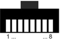
| 1 (White/Orange) | +5V Ground |
| 2 (Orange) | +5V |
| 3 (White/Green) | Aux Return |
| 4 (Blue) | 1-Wire Data |
| 5 (White/Blue) | 1-Wire Ground |
| 6 (Green) | Aux |
| 7 (White/Brown) | +12V |
| 8 (Brown) | +12V Ground |
Wire colors according to T568B
Devices with RJ12 Connectors
Some manufacturers use RJ12 connectors on their devices. Compared to RJ45 connectors, RJ12 only provides six wires. Since RJ12 plugs can mechanically be inserted into RJ45 sockets, the pin assignments of the connected devices should be checked carefully.
Comparing Pin Assignments
If you plan to combine 1-Wire products with connectors from different manufacturers, you should carefully compare the pin assignments of the devices involved. The pin assignment can usually be found in the product description on our website or in the datasheet of the respective device.
If the pin assignments differ, special connection cables must be used. These cables can easily be made using RJ12 or RJ45 modular connectors and a crimping tool.
Examples of Different Pin Assignments
The following examples illustrate what can happen if products from different manufacturers are connected without verifying their pin assignments.
Be Careful with 1-Wire Bus Power Supplies
When using a power supply for the 1-Wire bus, for example the MS-PWR from iButtonLink, special attention must be paid to the correct pin assignment of the connected devices. On the MS-PWR all pins are used and assigned to specific functions.
A critical combination would be using a cable temperature sensor from the OW-Temp Series with RJ12 connector from EDS together with the MS-PWR 1-Wire power supply with RJ45 connector from iButtonLink.
When comparing the pin assignments of both devices it becomes clear that the temperature sensor expects a 5V supply on pin 6 of the RJ12 connector, while the MS-PWR provides 12V on this pin. When an RJ12 plug is inserted into an RJ45 socket, pin 6 of the RJ12 connector connects to pin 7 of the RJ45 socket.
According to the 1-Wire standard, pin 7 is reserved for devices requiring a 12V supply. Since the MS-PWR follows this standard, 12V is present on this pin. As a result, the temperature sensor receives 12V instead of the specified 5V.
This leads to a failure of the temperature sensor within a few seconds. The metal housing of the sensor also becomes extremely hot.
Missing Power Supply on 1-Wire Devices
A combination that does not cause damage but should still be avoided is using the OW-SERVER-ENET from EDS as the 1-Wire bus master together with the T-Sense temperature sensor from iButtonLink.
The T-Sense temperature sensor expects a 5V supply on pin 2 of the RJ45 connector. The OW-SERVER-ENET, however, provides the 5V supply on pin 6 of its RJ12 connector.
When using an RJ12 cable, pin 6 of the RJ12 connector connects to pin 7 of the RJ45 connector on the T-Sense. Since pin 7 on the T-Sense is not connected, the sensor receives no power supply, resulting in unreliable operation.
To operate the T-Sense sensor with the OW-SERVER-ENET, a special cable is required that connects pin 6 of the RJ12 connector on the OW-SERVER-ENET to pin 2 of the RJ45 connector on the T-Sense. Such a cable may need to be assembled manually.
OW-Server and 1-Wire Power Supply
The OW-SERVER-ENET only provides a 5V supply for 1-Wire devices. If devices requiring a 12V supply are to be used, an additional power supply is required, such as the MS-PWR from iButtonLink.
The MS-PWR is directly compatible with 1-Wire bus masters from Maxim Integrated, iButtonLink and Eclo. In these cases it can simply be connected to the bus master using an RJ45 or RJ12-to-RJ45 cable.
To use the MS-PWR together with the OW-SERVER-ENET, a two-wire connection cable is required. This cable connects pins 3 and 4 of the RJ12 connector on the OW-SERVER-ENET with pins 4 and 5 on the MS-PWR. In this configuration only the 1-Wire signal is transferred from the OW-SERVER-ENET, while the MS-PWR distributes the signals according to the 1-Wire standard.
Conclusion
Combining 1-Wire products with connectors from different manufacturers is generally possible. However, special connection cables may be required in some cases. By carefully checking the pin assignments of the devices involved, such problems can easily be avoided and reliable operation of the 1-Wire network can be ensured.